
MORryde TV40-010H Ceiling Slide-Out Flip-Down TV Mount - 35 lb


Ready to order
MORryde TV40-010H Ceiling Slide-Out Flip-Down TV Mount - 35 lb
---
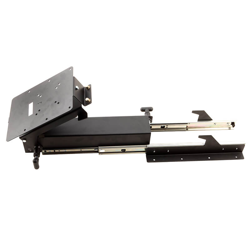
MORryde TV40-010H is a slide-out, flip-down ceiling TV mount for a TV or monitor up to 35 lb, commonly installed inside an RV basement cargo bay. The compartment size also limits the TV that can be installed. Match the actual model label, TV weight, TV hole pattern and reinforced supporting structure; screen size alone does not establish fit.
- 35 lb TV capacity; reinforced horizontal surface or ceiling installation
- Archived catalog: 17-inch slide travel; current page: 130° swivel, not specified per direction
- Two release handles: slide out, then support TV while releasing flip-down latch
- Stow TV into locked up position, then release slide and retract into bay; verify actual clearance and hardware
Slide, flip-down and swivel movement
Archived MORryde catalog page 24 specifies 17 inches of slide travel and swivel/tilt. The current product page specifies 130° swivel without saying 130° in each direction. Do not double that figure into a 260° sweep. The reviewed manual shows sliding out before releasing the flip-down mechanism; it does not give a separate numeric drop, flip or tilt range. Available TV movement depends on the compartment, TV body, cables and other obstructions.
TV holes and optional adapter
The exact manual describes VESA hole patterns up to 200×200 mm; the current page identifies 200×200 mm. Verify the actual TV and plate holes, thread, allowed insertion depth and rear recess rather than assuming every smaller pattern is supported. Both the manual and current page mention an optional 200×400 mm adapter, not an included adapter. Its exact service part number and verified ERVP catalog pairing remain unconfirmed. An adapter does not increase the mount’s 35 lb TV rating or remove cargo-bay clearance limits.
Reinforced horizontal surface or ceiling
The manual specifies a horizontal supporting surface or ceiling, usually inside a basement cargo bay. The structure must support five times the combined TV-and-mount weight and may need reinforcement. Brick, concrete and concrete block are excluded. Attach the bracket using the manual’s top-view mounting-hole layout and suitable structural fasteners. This ceiling slide is not the vertical-wall installation documented for TV40-011H or TV40-002H.
Cargo-bay clearance and spacing
The manual notes that spacing the mount away from the ceiling may be necessary for it to slide clear of the cargo bay. No spacer thickness or approved spacer part number is given. Check the bay opening, door/lip, handle, full slide and flip-down path, TV body and rear cables, plus room to operate both handles. Reinforcement, spacing and fastener length must be appropriate to the actual structure; do not borrow another mount’s adjustable-depth dimension.
TV plate attachment
Align the TV hole pattern with the mounting plate as near the center as possible and secure it with suitable bolts, washers and optional spacers where the TV’s recessed holes require them. The manual says this can be done without removing the plate; the separated plate in the illustration does not establish a portable docking interface. Remove the TV’s original stand according to its own instructions. Two people may be needed to lift and secure the TV safely.
Deploying the TV
To deploy, the manual shows pulling the slide-release handle and sliding the mount out of the cargo bay. Then pull the second handle to release the TV and flip it down, supporting the TV so it lowers slowly. Keep hands on the TV and release handles during setup and stowing, clear of pinch points. Use the exact manual’s OUT diagram to distinguish the two handles; do not substitute another model’s single-handle or chain-release procedure.
Stowing for travel
To stow, the manual’s IN diagram first shows returning the TV into place so it locks in the up position for travel. Then pull the slide-release handle and slide the assembly into the cargo bay. Verify the TV is locked up and the slide is fully stowed before vehicle movement; do not travel with it deployed. The reviewed instructions do not prescribe a separate added restraint or lock test force. Exact replacement handles, latches, slides and hinge/service part numbers remain unconfirmed.
Illustrated hardware and actual supplied pack
The manual illustrates four each M4×12/30, M5×12/30, M6×12/35 and M8×12/35 mm TV bolts, six each M4/M5/M6/M8 lock washers, six #10 washers, and four each optional M4/M5 and M6 spacers. For structural attachment it illustrates eight each 1/4×1 inch self-drilling screws, 1/4×1 inch lag bolts, 1/4×1-1/2 inch lag bolts and 1/4-inch ID washers. Step 1 calls for 1/8-inch pilot holes for 1/4-inch lag bolts, or self-drilling screws depending on the surface, with washers. Select hardware for the structure and TV; not every illustrated fastener is used in every installation. Excessive length can puncture interior or exterior structure. Actual supplied pack/revision and any extra TV-specific hardware remain unconfirmed.
Dimensions and net-weight limits
Archived MORryde catalog page 24 gives 8 W × 7.5 H inches, with overall depth from 21 inches minimum to 38 inches maximum; it separately lists 17-inch slide travel. Overall depth, travel and the TV’s installed envelope are different measurements. The previous 14 W × 9 H × 22 L inch display and 24/25 lb shipping/physical figures were not verified as this mount’s net dimensions or weight. Operational measurement fields are retained separately; use the actual assembly and supplied revision to plan installation. Exact net weight and fully installed clearance remain unconfirmed.
Manual and gallery identity
The PDF currently linked by MORryde and the retained Shopify-hosted instructions are byte-for-byte identical, including the two-page installation and operation diagrams. They are the same reviewed instructions, not two established hardware revisions. The first two gallery entries are also identical images; the third shows the compact assembly. Existing gallery order and files are preserved.
Service parts and replacement fit
An optional 200×400 mm adapter is documented, but no exact service part number or supported product-to-product pairing was established. MORryde’s TV54-014H adapter page and catalog describe larger VESA patterns generically; neither reviewed source names a TV40-010H-specific connection. Shared VESA dimensions or comparison links do not prove matching rail, plate, wall/ceiling holes, interchangeable latches or replacement fit. No new fitment relationship is asserted.
Installation and operation instructions
TV40-010H manufacturer installation and operation instructions · Archived MORryde catalog, page 24
Compare separate TV mount designs
These links compare designs and do not establish interchangeable hardware or replacement fit.
| Weight capacity (pounds) | 35 |
|---|---|
| Archived slide travel (inches) | 17 |
| Swivel on current manufacturer page (degrees) | 130 |
| Swivel/flip/tilt limits | Archived MORryde catalog page 24 specifies 17 inches of slide travel and swivel/tilt. The current product page specifies 130° swivel without saying 130° in each direction. Do not double that figure into a 260° sweep. The reviewed manual shows sliding out before releasing the flip-down mechanism; it does not give a separate numeric drop, flip or tilt range. Available TV movement depends on the compartment, TV body, cables and other obstructions. |
| Vesa pattern and optional adapter | The exact manual describes VESA hole patterns up to 200×200 mm; the current page identifies 200×200 mm. Verify the actual TV and plate holes, thread, allowed insertion depth and rear recess rather than assuming every smaller pattern is supported. Both the manual and current page mention an optional 200×400 mm adapter, not an included adapter. Its exact service part number and verified ERVP catalog pairing remain unconfirmed. An adapter does not increase the mount’s 35 lb TV rating or remove cargo-bay clearance limits. |
| Archived overall dimensions and net-weight limits | Archived MORryde catalog page 24 gives 8 W × 7.5 H inches, with overall depth from 21 inches minimum to 38 inches maximum; it separately lists 17-inch slide travel. Overall depth, travel and the TV’s installed envelope are different measurements. The previous 14 W × 9 H × 22 L inch display and 24/25 lb shipping/physical figures were not verified as this mount’s net dimensions or weight. Operational measurement fields are retained separately; use the actual assembly and supplied revision to plan installation. Exact net weight and fully installed clearance remain unconfirmed. |
| Horizontal support and orientation | The manual specifies a horizontal supporting surface or ceiling, usually inside a basement cargo bay. The structure must support five times the combined TV-and-mount weight and may need reinforcement. Brick, concrete and concrete block are excluded. Attach the bracket using the manual’s top-view mounting-hole layout and suitable structural fasteners. This ceiling slide is not the vertical-wall installation documented for TV40-011H or TV40-002H. |
| Cargo-bay clearance | The manual notes that spacing the mount away from the ceiling may be necessary for it to slide clear of the cargo bay. No spacer thickness or approved spacer part number is given. Check the bay opening, door/lip, handle, full slide and flip-down path, TV body and rear cables, plus room to operate both handles. Reinforcement, spacing and fastener length must be appropriate to the actual structure; do not borrow another mount’s adjustable-depth dimension. |
| Tv plate attachment | Align the TV hole pattern with the mounting plate as near the center as possible and secure it with suitable bolts, washers and optional spacers where the TV’s recessed holes require them. The manual says this can be done without removing the plate; the separated plate in the illustration does not establish a portable docking interface. Remove the TV’s original stand according to its own instructions. Two people may be needed to lift and secure the TV safely. |
| Deployment sequence | To deploy, the manual shows pulling the slide-release handle and sliding the mount out of the cargo bay. Then pull the second handle to release the TV and flip it down, supporting the TV so it lowers slowly. Keep hands on the TV and release handles during setup and stowing, clear of pinch points. Use the exact manual’s OUT diagram to distinguish the two handles; do not substitute another model’s single-handle or chain-release procedure. |
| Stowing and travel | To stow, the manual’s IN diagram first shows returning the TV into place so it locks in the up position for travel. Then pull the slide-release handle and slide the assembly into the cargo bay. Verify the TV is locked up and the slide is fully stowed before vehicle movement; do not travel with it deployed. The reviewed instructions do not prescribe a separate added restraint or lock test force. Exact replacement handles, latches, slides and hinge/service part numbers remain unconfirmed. |
| Illustrated hardware and actual pack | The manual illustrates four each M4×12/30, M5×12/30, M6×12/35 and M8×12/35 mm TV bolts, six each M4/M5/M6/M8 lock washers, six #10 washers, and four each optional M4/M5 and M6 spacers. For structural attachment it illustrates eight each 1/4×1 inch self-drilling screws, 1/4×1 inch lag bolts, 1/4×1-1/2 inch lag bolts and 1/4-inch ID washers. Step 1 calls for 1/8-inch pilot holes for 1/4-inch lag bolts, or self-drilling screws depending on the surface, with washers. Select hardware for the structure and TV; not every illustrated fastener is used in every installation. Excessive length can puncture interior or exterior structure. Actual supplied pack/revision and any extra TV-specific hardware remain unconfirmed. |
| Manual and gallery identity | The PDF currently linked by MORryde and the retained Shopify-hosted instructions are byte-for-byte identical, including the two-page installation and operation diagrams. They are the same reviewed instructions, not two established hardware revisions. The first two gallery entries are also identical images; the third shows the compact assembly. Existing gallery order and files are preserved. |
| Service parts and fitment limits | An optional 200×400 mm adapter is documented, but no exact service part number or supported product-to-product pairing was established. MORryde’s TV54-014H adapter page and catalog describe larger VESA patterns generically; neither reviewed source names a TV40-010H-specific connection. Shared VESA dimensions or comparison links do not prove matching rail, plate, wall/ceiling holes, interchangeable latches or replacement fit. No new fitment relationship is asserted. |
- What is the maximum weight capacity of the morryde tv40-010h ceiling tv mount? MORryde TV40-010H is a slide-out, flip-down ceiling TV mount for a TV or monitor up to 35 lb, commonly installed inside an RV basement cargo bay. The compartment size also limits the TV that can be installed. Match the actual model label, TV weight, TV hole pattern and reinforced supporting structure; screen size alone does not establish fit.
- Can this tv mount swivel and what is the range of motion? Archived MORryde catalog page 24 specifies 17 inches of slide travel and swivel/tilt. The current product page specifies 130° swivel without saying 130° in each direction. Do not double that figure into a 260° sweep. The reviewed manual shows sliding out before releasing the flip-down mechanism; it does not give a separate numeric drop, flip or tilt range. Available TV movement depends on the compartment, TV body, cables and other obstructions.
- What vesa mounting patterns are compatible with this tv mount? The exact manual describes VESA hole patterns up to 200×200 mm; the current page identifies 200×200 mm. Verify the actual TV and plate holes, thread, allowed insertion depth and rear recess rather than assuming every smaller pattern is supported. Both the manual and current page mention an optional 200×400 mm adapter, not an included adapter. Its exact service part number and verified ERVP catalog pairing remain unconfirmed. An adapter does not increase the mount’s 35 lb TV rating or remove cargo-bay clearance limits.
- Does the package include all the necessary hardware for installation? The manual illustrates four each M4×12/30, M5×12/30, M6×12/35 and M8×12/35 mm TV bolts, six each M4/M5/M6/M8 lock washers, six #10 washers, and four each optional M4/M5 and M6 spacers. For structural attachment it illustrates eight each 1/4×1 inch self-drilling screws, 1/4×1 inch lag bolts, 1/4×1-1/2 inch lag bolts and 1/4-inch ID washers. Step 1 calls for 1/8-inch pilot holes for 1/4-inch lag bolts, or self-drilling screws depending on the surface, with washers. Select hardware for the structure and TV; not every illustrated fastener is used in every installation. Excessive length can puncture interior or exterior structure. Actual supplied pack/revision and any extra TV-specific hardware remain unconfirmed. The PDF currently linked by MORryde and the retained Shopify-hosted instructions are byte-for-byte identical, including the two-page installation and operation diagrams. They are the same reviewed instructions, not two established hardware revisions. The first two gallery entries are also identical images; the third shows the compact assembly. Existing gallery order and files are preserved.
- Is this tv mount suitable for mounting in an rv cargo bay? The manual specifies a horizontal supporting surface or ceiling, usually inside a basement cargo bay. The structure must support five times the combined TV-and-mount weight and may need reinforcement. Brick, concrete and concrete block are excluded. Attach the bracket using the manual’s top-view mounting-hole layout and suitable structural fasteners. This ceiling slide is not the vertical-wall installation documented for TV40-011H or TV40-002H. The manual notes that spacing the mount away from the ceiling may be necessary for it to slide clear of the cargo bay. No spacer thickness or approved spacer part number is given. Check the bay opening, door/lip, handle, full slide and flip-down path, TV body and rear cables, plus room to operate both handles. Reinforcement, spacing and fastener length must be appropriate to the actual structure; do not borrow another mount’s adjustable-depth dimension.
- How do i release, flip down and stow tv40-010h for travel? To deploy, the manual shows pulling the slide-release handle and sliding the mount out of the cargo bay. Then pull the second handle to release the TV and flip it down, supporting the TV so it lowers slowly. Keep hands on the TV and release handles during setup and stowing, clear of pinch points. Use the exact manual’s OUT diagram to distinguish the two handles; do not substitute another model’s single-handle or chain-release procedure. To stow, the manual’s IN diagram first shows returning the TV into place so it locks in the up position for travel. Then pull the slide-release handle and slide the assembly into the cargo bay. Verify the TV is locked up and the slide is fully stowed before vehicle movement; do not travel with it deployed. The reviewed instructions do not prescribe a separate added restraint or lock test force. Exact replacement handles, latches, slides and hinge/service part numbers remain unconfirmed.
- What dimensions, plate attachment and service-part limits should i check? Archived MORryde catalog page 24 gives 8 W × 7.5 H inches, with overall depth from 21 inches minimum to 38 inches maximum; it separately lists 17-inch slide travel. Overall depth, travel and the TV’s installed envelope are different measurements. The previous 14 W × 9 H × 22 L inch display and 24/25 lb shipping/physical figures were not verified as this mount’s net dimensions or weight. Operational measurement fields are retained separately; use the actual assembly and supplied revision to plan installation. Exact net weight and fully installed clearance remain unconfirmed. Align the TV hole pattern with the mounting plate as near the center as possible and secure it with suitable bolts, washers and optional spacers where the TV’s recessed holes require them. The manual says this can be done without removing the plate; the separated plate in the illustration does not establish a portable docking interface. Remove the TV’s original stand according to its own instructions. Two people may be needed to lift and secure the TV safely. An optional 200×400 mm adapter is documented, but no exact service part number or supported product-to-product pairing was established. MORryde’s TV54-014H adapter page and catalog describe larger VESA patterns generically; neither reviewed source names a TV40-010H-specific connection. Shared VESA dimensions or comparison links do not prove matching rail, plate, wall/ceiling holes, interchangeable latches or replacement fit. No new fitment relationship is asserted.
Product Documents & Manuals
Ready to order
MORryde TV40-010H Ceiling Slide-Out Flip-Down TV Mount - 35 lb
Loading customer reviews…

Factory-Fresh OEM Parts — the same brands installed in new RVs straight from Elkhart. Genuine, name-brand components made to order — never generic, never outdated. Sourced directly from the original RV manufacturers for perfect fit and factory-level quality.