
MORryde TV1-080H Drop-Down Ceiling TV Mount - 25 lb, Up to 24-inch TV


Ready to order
MORryde TV1-080H Drop-Down Ceiling TV Mount - 25 lb, Up to 24-inch TV
---
MORryde TV1-080H is a drop-down ceiling TV mount rated for a TV up to 25 lb and advertised for screens up to 24 inches. Both the TV’s weight and size limits apply; the actual VESA holes, cabinet space, TV body and reinforced supporting structure must also match. Screen size alone does not establish fit.
- 25 lb TV limit and up to 24-inch screen; verify actual holes and clearance
- VERSION 2 VESA: 75×75, 100×100, 100×200 and 200×200 mm
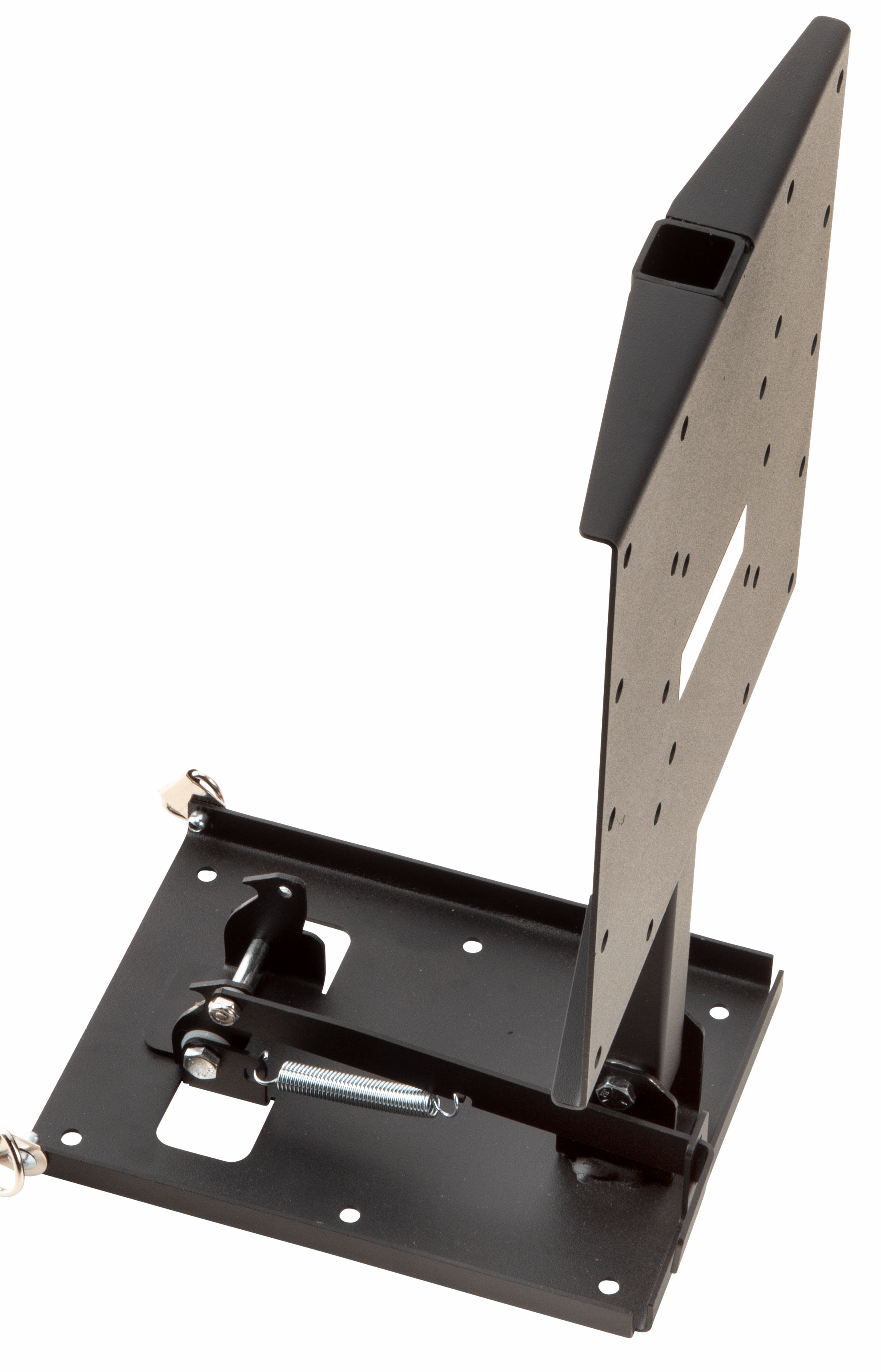
- Support TV, pull lever and gently lower; lift toward ceiling until travel latch engages
- Reinforced horizontal/ceiling support must hold five times combined TV-and-mount weight; actual hardware revision must match
Friction pivot and motion limits
The friction pivot lets the TV move up and down and be positioned for viewing. The exact current manual does not specify a numeric drop, tilt or horizontal swivel range, or a sliding stroke. Its parts list includes the words Double-Jointed Extension Arm, but its operating diagram shows the ceiling fold-down mechanism; a separate double-jointed extension reach is not established. Do not transfer the slide travel, two-handle operation or swivel angles of TV40-010H or another mount to TV1-080H.
VESA holes and optional adapter
The current manual, internally marked VERSION 2, lists 75×75, 100×100, 100×200 and 200×200 mm VESA patterns. Match the actual plate and TV holes, screw thread, permitted insertion depth and rear recess. The older instructions describe patterns up to 200×200 mm. The current product page mentions an optional 200×400 mm adapter; its exact part number, supplied inclusion and verified ERVP listing match are unconfirmed. An adapter does not increase the 25 lb rating or establish fit for a TV larger than the stated limit.
Reinforced ceiling support
Use the exact manual’s reinforced horizontal supporting surface or ceiling installation. It requires support for five times the combined TV-and-mount weight and excludes brick, concrete and concrete block. Step 1 shows the top-view mounting-hole layout, 1/8-inch pilot holes, 1/4-inch lag bolts and 1/4-inch washers, or hardware appropriate to the structure. A brief introductory reference to a wall does not establish a separate vertical-wall installation; the safety section and installation step describe horizontal/ceiling support. Verify reinforcement and fastener engagement.
Lowering, stowing and travel
To lower the TV, support it with one hand, pull the release lever and gently guide it into the vertical position. To stow it, gently lift the TV toward the ceiling and let it lock into place. The product page identifies a spring-loaded slam latch for storage during travel. Verify engagement before driving; the friction pivot alone is not proof that the travel latch is engaged. Support the TV and keep fingers clear of the moving pivot and latch. No extra transport restraint, latch-test force or pivot-tension adjustment procedure is established by the reviewed instructions.
Bolted TV plate
Align the TV holes with the matching holes in the mounting plate and secure the TV with suitable bolts and washers. Remove any original TV stand according to the TV’s own instructions. Two people may be needed to lift and secure the TV. The bolted TV plate is not a documented portable docking interface; removing the television or changing the ceiling plate is not an approved quick-release operation in these instructions.
Current manual hardware
The current VERSION 2 manual illustrates four each M4×12, M5×12 and M6×12 mm TV bolts; eight 1/4×1 inch lag bolts; and eight each M6, #10 and 1/4-inch flat washers. Select TV screw thread and permitted insertion depth from the TV’s instructions. The actual supplied pack/revision and any extra hardware required for a recessed TV remain unconfirmed. Fasteners that are too long may puncture exterior structure.
Older instructions and revision limits
The retained older TV1-080H manual also states 25 lb and up to 200×200 mm VESA, but shows M4/M5×12/30 mm TV bolts, six each M4 and M5 lock washers and four #10 washers. It illustrates a wood-application lag fastener without establishing a universal length or pack quantity. Its surface restriction also excludes steel, in addition to masonry; VERSION 2’s corresponding note excludes masonry. Use the instructions appropriate to the actual unit and supporting structure. The file name ending in v3 is internally labeled VERSION 2, not a verified third hardware revision.
Up/down dimensions and clearance
The current manufacturer page gives overall up-position dimensions of 8.6 W × 2.3 H × 14.6 D inches and down-position dimensions of 8.6 W × 14.75 H × 5.6 D inches. Archived catalog page 24 gives 8.6 W × 14.77 H × 5.58 D inches down, a small published rounding difference. Check the actual assembly, TV back, cables, cabinet door, fold path and release-lever access; these mount dimensions do not certify the full installed TV envelope. Existing operational shipping measurements remain separate. Net product weight and installation-specific clearance have not been independently established.
Gallery identification
Both retained gallery views show the fold-down assembly, its spring and the TV plate; one visible plate label gives a 25 lb maximum load. The gallery is preserved. A visible spring or retaining pin does not establish its service part number, a tension setting, or compatibility with another mount.
Replacement and service parts
An exact replacement spring, lever, latch, pivot, TV plate or adapter part number and a supported existing-catalog pairing have not been established. Generic MORryde adapter descriptions and shared VESA dimensions do not prove a specific interface, matching ceiling holes or a drop-in replacement. Existing comparison links describe separate designs; they do not approve interchangeable hardware.
Instructions by revision
TV1-080H current MORryde instructions — internally VERSION 2 · TV1-080H older instructions — hardware and surface reference · Archived MORryde catalog, page 24
Compare separate TV mount designs
These links compare designs and do not establish interchangeable hardware or replacement fit.
| Weight capacity (pounds) | 25 |
|---|---|
| Maximum stated tv size (inches) | 24 |
| Vesa patterns in version 2 (mm) | 75×75; 100×100; 100×200; 200×200 |
| Overall up-position dimensions (w × h × d inches) | 8.6 × 2.3 × 14.6 — current manufacturer page |
| Overall down-position dimensions (w × h × d inches) | 8.6 × 14.75 × 5.6 — current manufacturer page |
| Dimensions, rounding and clearance | The current manufacturer page gives overall up-position dimensions of 8.6 W × 2.3 H × 14.6 D inches and down-position dimensions of 8.6 W × 14.75 H × 5.6 D inches. Archived catalog page 24 gives 8.6 W × 14.77 H × 5.58 D inches down, a small published rounding difference. Check the actual assembly, TV back, cables, cabinet door, fold path and release-lever access; these mount dimensions do not certify the full installed TV envelope. Existing operational shipping measurements remain separate. Net product weight and installation-specific clearance have not been independently established. |
| Motion limits | The friction pivot lets the TV move up and down and be positioned for viewing. The exact current manual does not specify a numeric drop, tilt or horizontal swivel range, or a sliding stroke. Its parts list includes the words Double-Jointed Extension Arm, but its operating diagram shows the ceiling fold-down mechanism; a separate double-jointed extension reach is not established. Do not transfer the slide travel, two-handle operation or swivel angles of TV40-010H or another mount to TV1-080H. |
| Ceiling support and fasteners | Use the exact manual’s reinforced horizontal supporting surface or ceiling installation. It requires support for five times the combined TV-and-mount weight and excludes brick, concrete and concrete block. Step 1 shows the top-view mounting-hole layout, 1/8-inch pilot holes, 1/4-inch lag bolts and 1/4-inch washers, or hardware appropriate to the structure. A brief introductory reference to a wall does not establish a separate vertical-wall installation; the safety section and installation step describe horizontal/ceiling support. Verify reinforcement and fastener engagement. |
| Release and travel latch | To lower the TV, support it with one hand, pull the release lever and gently guide it into the vertical position. To stow it, gently lift the TV toward the ceiling and let it lock into place. The product page identifies a spring-loaded slam latch for storage during travel. Verify engagement before driving; the friction pivot alone is not proof that the travel latch is engaged. Support the TV and keep fingers clear of the moving pivot and latch. No extra transport restraint, latch-test force or pivot-tension adjustment procedure is established by the reviewed instructions. |
| Tv plate attachment | Align the TV holes with the matching holes in the mounting plate and secure the TV with suitable bolts and washers. Remove any original TV stand according to the TV’s own instructions. Two people may be needed to lift and secure the TV. The bolted TV plate is not a documented portable docking interface; removing the television or changing the ceiling plate is not an approved quick-release operation in these instructions. |
| Current illustrated hardware | The current VERSION 2 manual illustrates four each M4×12, M5×12 and M6×12 mm TV bolts; eight 1/4×1 inch lag bolts; and eight each M6, #10 and 1/4-inch flat washers. Select TV screw thread and permitted insertion depth from the TV’s instructions. The actual supplied pack/revision and any extra hardware required for a recessed TV remain unconfirmed. Fasteners that are too long may puncture exterior structure. |
| Older revision and surface restriction | The retained older TV1-080H manual also states 25 lb and up to 200×200 mm VESA, but shows M4/M5×12/30 mm TV bolts, six each M4 and M5 lock washers and four #10 washers. It illustrates a wood-application lag fastener without establishing a universal length or pack quantity. Its surface restriction also excludes steel, in addition to masonry; VERSION 2’s corresponding note excludes masonry. Use the instructions appropriate to the actual unit and supporting structure. The file name ending in v3 is internally labeled VERSION 2, not a verified third hardware revision. |
| Adapter and vesa limits | The current manual, internally marked VERSION 2, lists 75×75, 100×100, 100×200 and 200×200 mm VESA patterns. Match the actual plate and TV holes, screw thread, permitted insertion depth and rear recess. The older instructions describe patterns up to 200×200 mm. The current product page mentions an optional 200×400 mm adapter; its exact part number, supplied inclusion and verified ERVP listing match are unconfirmed. An adapter does not increase the 25 lb rating or establish fit for a TV larger than the stated limit. |
| Service parts and fitment | An exact replacement spring, lever, latch, pivot, TV plate or adapter part number and a supported existing-catalog pairing have not been established. Generic MORryde adapter descriptions and shared VESA dimensions do not prove a specific interface, matching ceiling holes or a drop-in replacement. Existing comparison links describe separate designs; they do not approve interchangeable hardware. |
- What is the maximum weight capacity of the morryde tv1-080h drop down ceiling tv mount? MORryde TV1-080H is a drop-down ceiling TV mount rated for a TV up to 25 lb and advertised for screens up to 24 inches. Both the TV’s weight and size limits apply; the actual VESA holes, cabinet space, TV body and reinforced supporting structure must also match. Screen size alone does not establish fit.
- What sizes of tvs does this drop down ceiling mount fit? MORryde TV1-080H is a drop-down ceiling TV mount rated for a TV up to 25 lb and advertised for screens up to 24 inches. Both the TV’s weight and size limits apply; the actual VESA holes, cabinet space, TV body and reinforced supporting structure must also match. Screen size alone does not establish fit. The current manufacturer page gives overall up-position dimensions of 8.6 W × 2.3 H × 14.6 D inches and down-position dimensions of 8.6 W × 14.75 H × 5.6 D inches. Archived catalog page 24 gives 8.6 W × 14.77 H × 5.58 D inches down, a small published rounding difference. Check the actual assembly, TV back, cables, cabinet door, fold path and release-lever access; these mount dimensions do not certify the full installed TV envelope. Existing operational shipping measurements remain separate. Net product weight and installation-specific clearance have not been independently established.
- Does the mount allow for adjusting the viewing angle of the tv? The friction pivot lets the TV move up and down and be positioned for viewing. The exact current manual does not specify a numeric drop, tilt or horizontal swivel range, or a sliding stroke. Its parts list includes the words Double-Jointed Extension Arm, but its operating diagram shows the ceiling fold-down mechanism; a separate double-jointed extension reach is not established. Do not transfer the slide travel, two-handle operation or swivel angles of TV40-010H or another mount to TV1-080H. To lower the TV, support it with one hand, pull the release lever and gently guide it into the vertical position. To stow it, gently lift the TV toward the ceiling and let it lock into place. The product page identifies a spring-loaded slam latch for storage during travel. Verify engagement before driving; the friction pivot alone is not proof that the travel latch is engaged. Support the TV and keep fingers clear of the moving pivot and latch. No extra transport restraint, latch-test force or pivot-tension adjustment procedure is established by the reviewed instructions.
- What mounting patterns does this tv mount support? The current manual, internally marked VERSION 2, lists 75×75, 100×100, 100×200 and 200×200 mm VESA patterns. Match the actual plate and TV holes, screw thread, permitted insertion depth and rear recess. The older instructions describe patterns up to 200×200 mm. The current product page mentions an optional 200×400 mm adapter; its exact part number, supplied inclusion and verified ERVP listing match are unconfirmed. An adapter does not increase the 25 lb rating or establish fit for a TV larger than the stated limit.
- What is included in the box with the tv mount? The current VERSION 2 manual illustrates four each M4×12, M5×12 and M6×12 mm TV bolts; eight 1/4×1 inch lag bolts; and eight each M6, #10 and 1/4-inch flat washers. Select TV screw thread and permitted insertion depth from the TV’s instructions. The actual supplied pack/revision and any extra hardware required for a recessed TV remain unconfirmed. Fasteners that are too long may puncture exterior structure. The retained older TV1-080H manual also states 25 lb and up to 200×200 mm VESA, but shows M4/M5×12/30 mm TV bolts, six each M4 and M5 lock washers and four #10 washers. It illustrates a wood-application lag fastener without establishing a universal length or pack quantity. Its surface restriction also excludes steel, in addition to masonry; VERSION 2’s corresponding note excludes masonry. Use the instructions appropriate to the actual unit and supporting structure. The file name ending in v3 is internally labeled VERSION 2, not a verified third hardware revision.
- How should tv1-080h attach to the ceiling and tv plate? Use the exact manual’s reinforced horizontal supporting surface or ceiling installation. It requires support for five times the combined TV-and-mount weight and excludes brick, concrete and concrete block. Step 1 shows the top-view mounting-hole layout, 1/8-inch pilot holes, 1/4-inch lag bolts and 1/4-inch washers, or hardware appropriate to the structure. A brief introductory reference to a wall does not establish a separate vertical-wall installation; the safety section and installation step describe horizontal/ceiling support. Verify reinforcement and fastener engagement. Align the TV holes with the matching holes in the mounting plate and secure the TV with suitable bolts and washers. Remove any original TV stand according to the TV’s own instructions. Two people may be needed to lift and secure the TV. The bolted TV plate is not a documented portable docking interface; removing the television or changing the ceiling plate is not an approved quick-release operation in these instructions.
- Can i use replacement latch, spring or adapter parts with tv1-080h? An exact replacement spring, lever, latch, pivot, TV plate or adapter part number and a supported existing-catalog pairing have not been established. Generic MORryde adapter descriptions and shared VESA dimensions do not prove a specific interface, matching ceiling holes or a drop-in replacement. Existing comparison links describe separate designs; they do not approve interchangeable hardware. Both retained gallery views show the fold-down assembly, its spring and the TV plate; one visible plate label gives a 25 lb maximum load. The gallery is preserved. A visible spring or retaining pin does not establish its service part number, a tension setting, or compatibility with another mount.
Ready to order
MORryde TV1-080H Drop-Down Ceiling TV Mount - 25 lb, Up to 24-inch TV
Loading customer reviews…

Factory-Fresh OEM Parts — the same brands installed in new RVs straight from Elkhart. Genuine, name-brand components made to order — never generic, never outdated. Sourced directly from the original RV manufacturers for perfect fit and factory-level quality.